Tees and Wyes Gallery
Component Placement
Used to place HVAC Tee and Wye components.
Accessed from the HVAC ribbon:
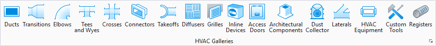
The following gallery displays which can be left floating or docked to the drawing area.
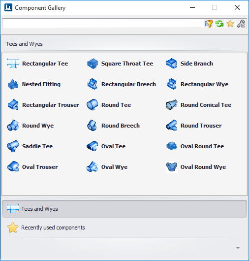
The following table shows the component options in the gallery along with the key in syntax. Selecting a tool from one of the placement galleries activates the Place Component dialog. The generic placement settings, along with the unique set of dimensional and data properties provide the core workflow used to accurately position equipment components in the model.


Select an option from the Tees taskbar/toolbox to display the Place Component dialog. This dialog is common to all HVAC components and allows you define a component's physical parameters as well as general properties before placement. The dialog remains open throughout the placement process.
In the Place Component dialog's Settings tab, select a placement point to determine which port serves as the placement point for the component. The options in the Placement Point list will vary depending on the component being placed. (Available Placement Points for Duct are Main_Port, Run_Port and Branch_Port) The HVAC Port Settings tab of the Place Component dialog allows you to define the End Preparations for the ports on the component to be placed. An example is shown below: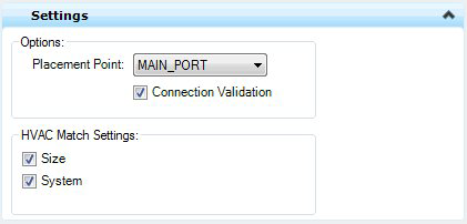

| End Prep | Defines which port to apply the EndPrep Type, Size and Length values to. You are able to define different values for each port if desired. |
| EndPrep Type | HVAC_Flange_End, HVAC_MALE_END, HVAC_Female_End, HVAC_Plain_End |
| EndPrep Size | Enter a size for the EndPrep Type. |
| Endprep Length | Enter length for the selected EndPrep Type. |
While enter/changing values in the fields, the component is dynamically updated in the drawing when move to the next field so you can see the changes before placing the component.
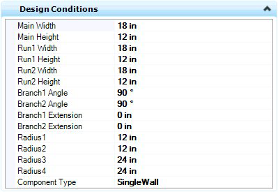
An example of the design conditions field for a Rectangular Wye is displayed below: Once the component parameter and property values are defined us the standard placement techniques to place the component in the drawing. Branching components will require a placement point and a direction for the branch port.